Jaw Type Coupling Assortment Procedure
The selection system for determining the correct jaw coupling size and elastomer requires working with the charts proven on the following pages. You’ll find 3 parts for being picked, two hubs and a single elastomer. Once the shaft size of the driver and driven of your application are of your exact same diameter, the hubs selected is going to be the same. When shaft diameters vary, hubs chosen will vary accordingly.
Facts important before a coupling might be chosen:
HP (or KW) and RPM or Torque of driver
Shaft sizes of driver and driven 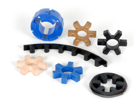 tools and corresponding keyways
Application description
Environmental disorders (i.e. excessive temperature, corrosive situations, room limitations)
Steps In Picking A Jaw Coupling
Phase one: Decide the Nominal Torque of your application by using the following formula:
Nominal Torque = in-lb = (HP x 63025)/RPM
Nm = (KW x 9550)/RPM
Step 2: Using the Application Support Factors Chart one decide on the support factor which very best corresponds to your application.
Step three: Determine the Layout Torque of one’s application by multiplying the Nominal Torque calculated in Step 1 from the Application Service Aspect determined in Phase 2.
Style Torque = Nominal Torque x Application Service Component
Stage four: Working with the Spider Overall performance Information Chart 2, choose the elastomer material which best corresponds for your application.
Step 5: Utilizing the Jaw Nominal Rated Torque Chart three , locate the ideal elastomer material column for that elastomer picked in Stage four.
Scan down this column to the very first entry wherever the Torque Worth from the suitable column is greater than or equal on the Layout Torque calculated in Stage three.
The moment this value is found, refer for the corresponding coupling dimension while in the 1st column with the Jaw Nominal Rated Torque Chart 3 .
Refer towards the optimum RPM worth for this elastomer torque capability to make sure that the application demands are met. In case the necessity just isn’t content at this point, another style of coupling could be essential for that application. Please seek advice from Lovejoy engineering for help.
Phase six: Examine the application driver/driven shaft sizes on the maximum bore size readily available over the coupling selected. If coupling bore dimension is not massive enough for your shaft diameter, decide on the following biggest coupling that may accommodate the driver/driven shaft diameters.
Phase seven: Applying the UPC amount assortment table , obtain the ideal Bore and Keyway sizes required and locate the amount.